Recitation
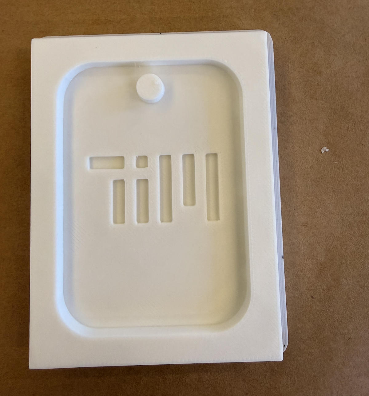
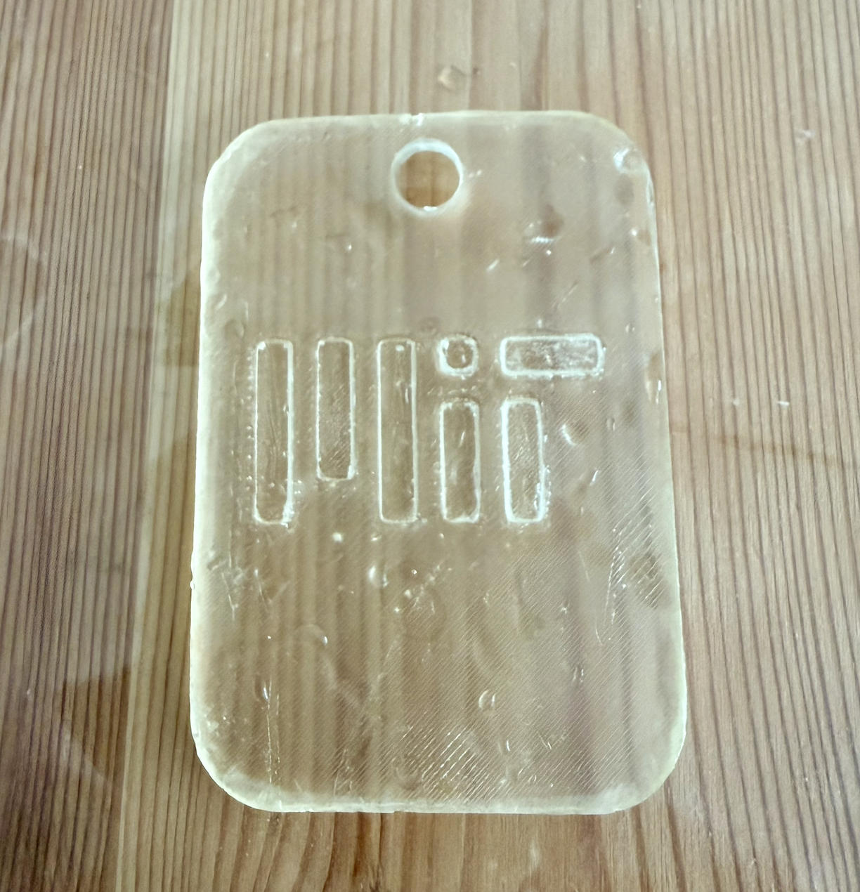
Project 1: Single-layer mold - MIT Logo Keychain
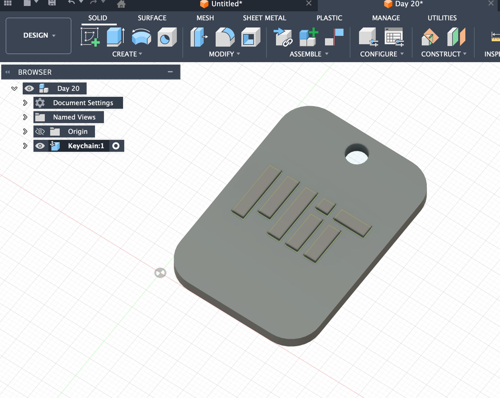
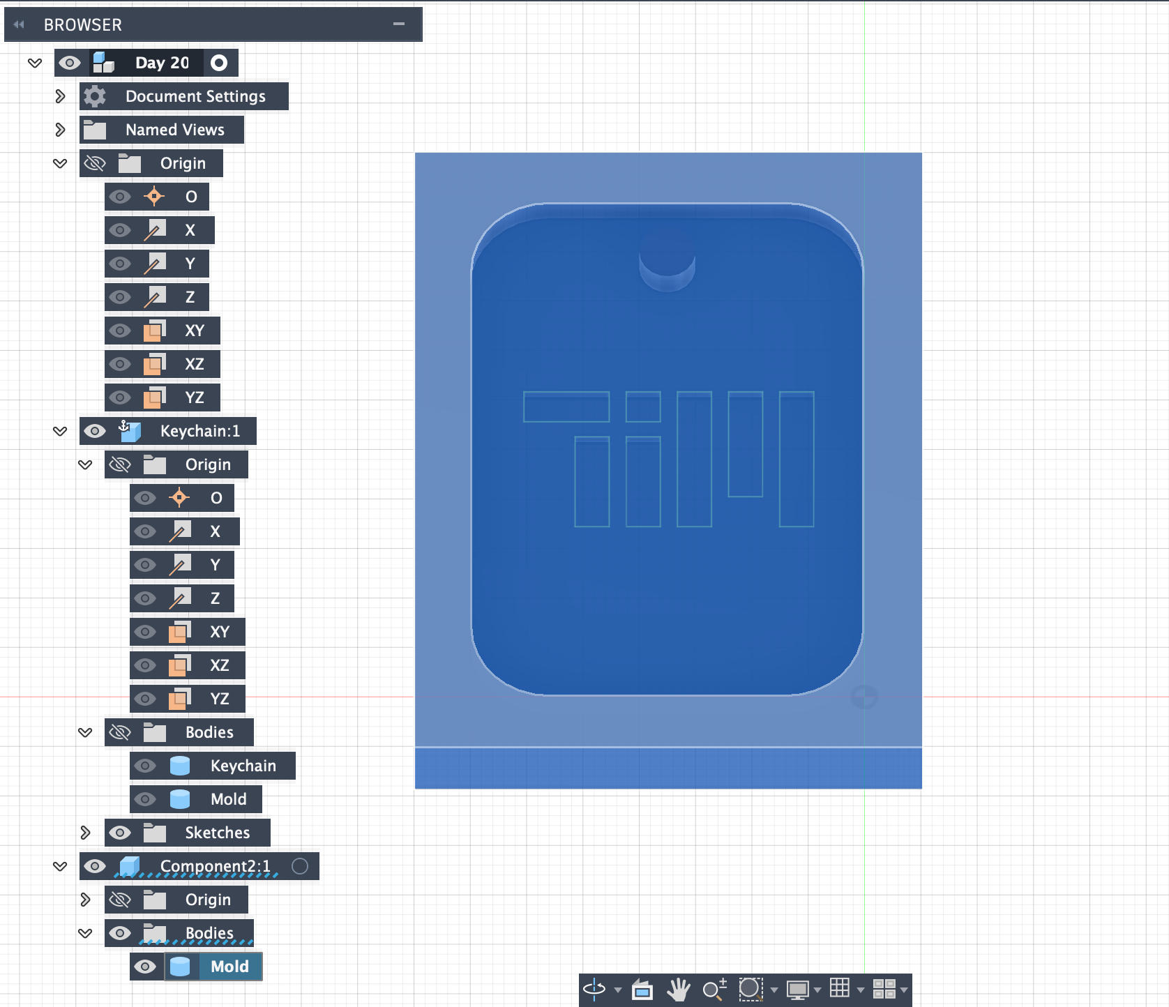
I started by designing a simple single-layer mold. I downloaded the MIT logo from the official MIT website (Kerberos login required) and used that Logo to create a keychain mold.
Draft Analysis in Fusion 360
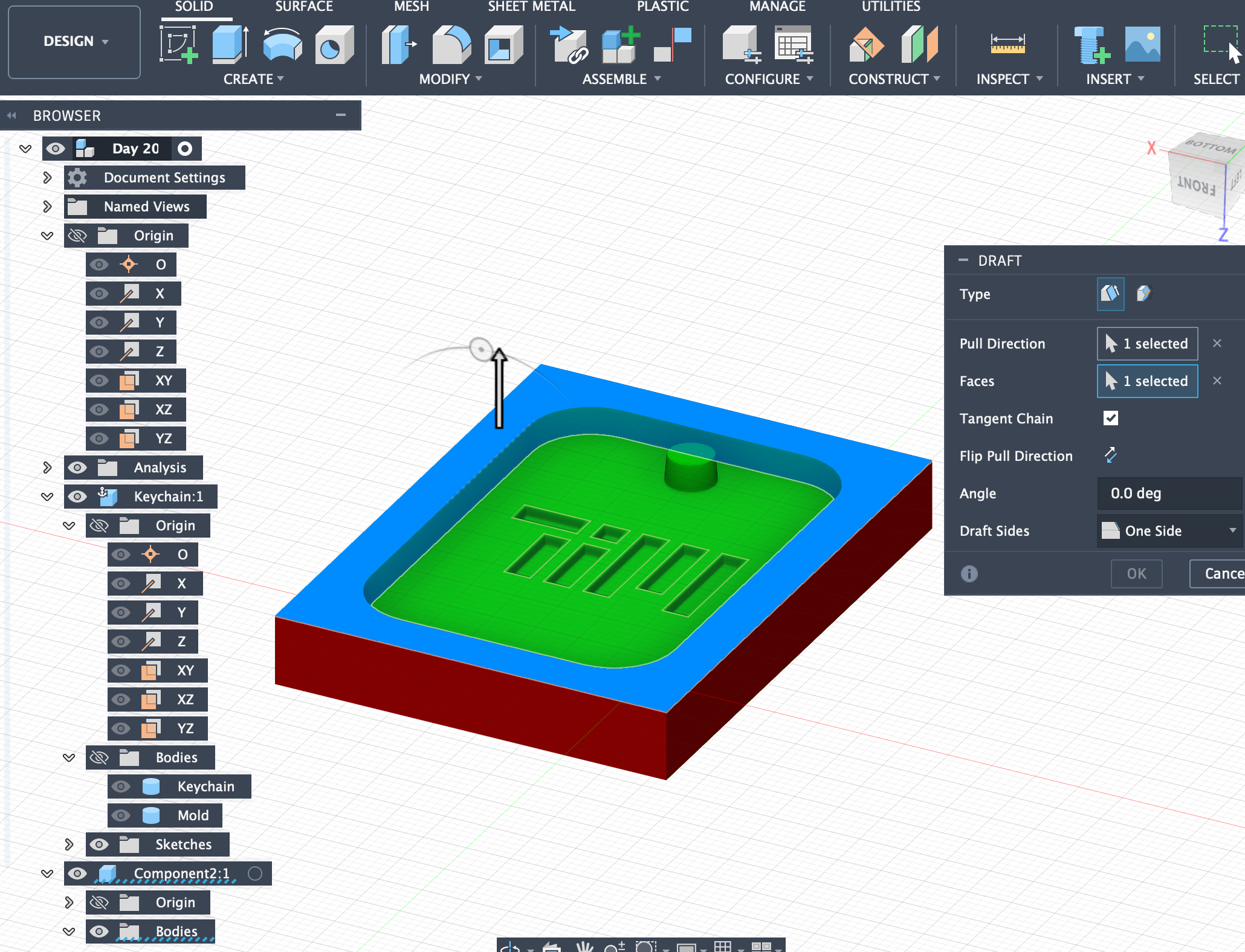
Draft Analysis in Fusion 360 visually checks whether your model has enough draft angle for molding or casting, so the part can be released from the mold without sticking or damaging the tool.
How to use it
Go to Inspect > Draft Analysis. Select the pull direction (the direction the part leaves the mold). Set a draft angle (e.g., 1–3°). Review the color feedback on your model.
Color meaning
Green – meets or exceeds required draft (good). Yellow – close to the required draft (borderline). Red – insufficient draft (may stick in the mold). Blue – negative draft (severe undercut/problem area).
In short, Draft Analysis helps you quickly spot and fix areas that would cause problems in molding or casting, so the design and manufacturing processes line up smoothly.
Files Download
Keychain Fusion file: download
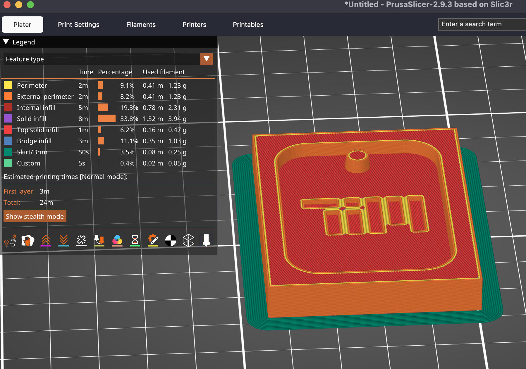
Keychain Fusion G-code: download
How to Separate an Imported STL into Two Parts in Fusion 360
When you import an STL into Fusion 360, it comes in as a mesh body (a bunch of triangles). For proper mold design, it's usually best to convert this mesh into a solid (BRep) body and then split it.
Method 1 (Recommended): Convert to Solid → Split Body
This is the standard workflow for mold-making.
Step 1 — Import the STL
Go to Insert → Insert Mesh. Select STL file and place it in the workspace.
Step 2 — Convert Mesh to Solid (BRep)
Fusion works best if the mesh has a reasonable number of triangles. If it's very dense, reduce it first.
Switch to the Mesh workspace. With the mesh selected, go to Modify → Reduce and lower the triangle count (aim for around 20k–50k triangles if possible).
Then go to Modify → Convert Mesh and choose BRep as the conversion type. After conversion, the body appears as a solid (BRep) body instead of a mesh.
Step 3 — Create a Cutting Plane
You need a plane that defines where the object will be split (this is often the mold parting line).
Use Construct → Midplane to split exactly in the middle, or use Construct → Offset Plane to position the plane where needed, or create a custom sketch and use it to define a splitting plane.
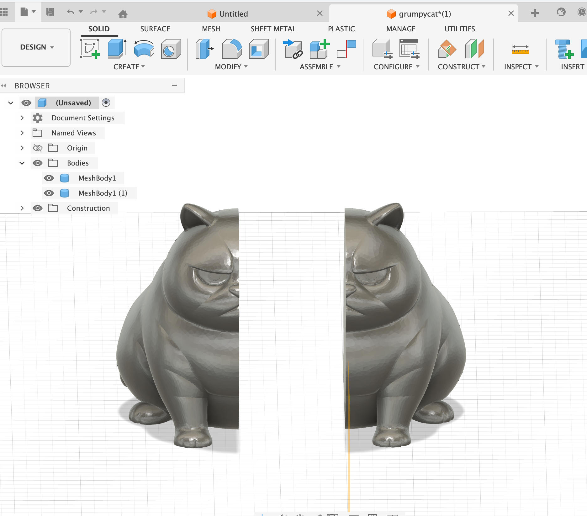
Step 4 — Split the Solid Body
Go to Modify → Split Body. Select your solid body as the Body to Split. Select the plane you created as the Splitting Tool. Confirm the command.
Fusion will create two separate solid bodies (e.g., Body1 and Body2), which you can then use as mold halves or further modify.
Method 2: Split the Mesh Directly (Plane Cut)
Use this if the STL is too heavy to convert, or if you just need a simple split and don't plan complex mold features.
Import the STL so it appears as a mesh body. Stay in the Mesh workspace. Go to Modify → Plane Cut. Position and rotate the cut plane for the split. Set the operation to Slice (not just cut one side). Confirm the command.
This will slice the mesh into two separate mesh bodies. Note that mesh bodies are less flexible for precise mold design compared to solid bodies.
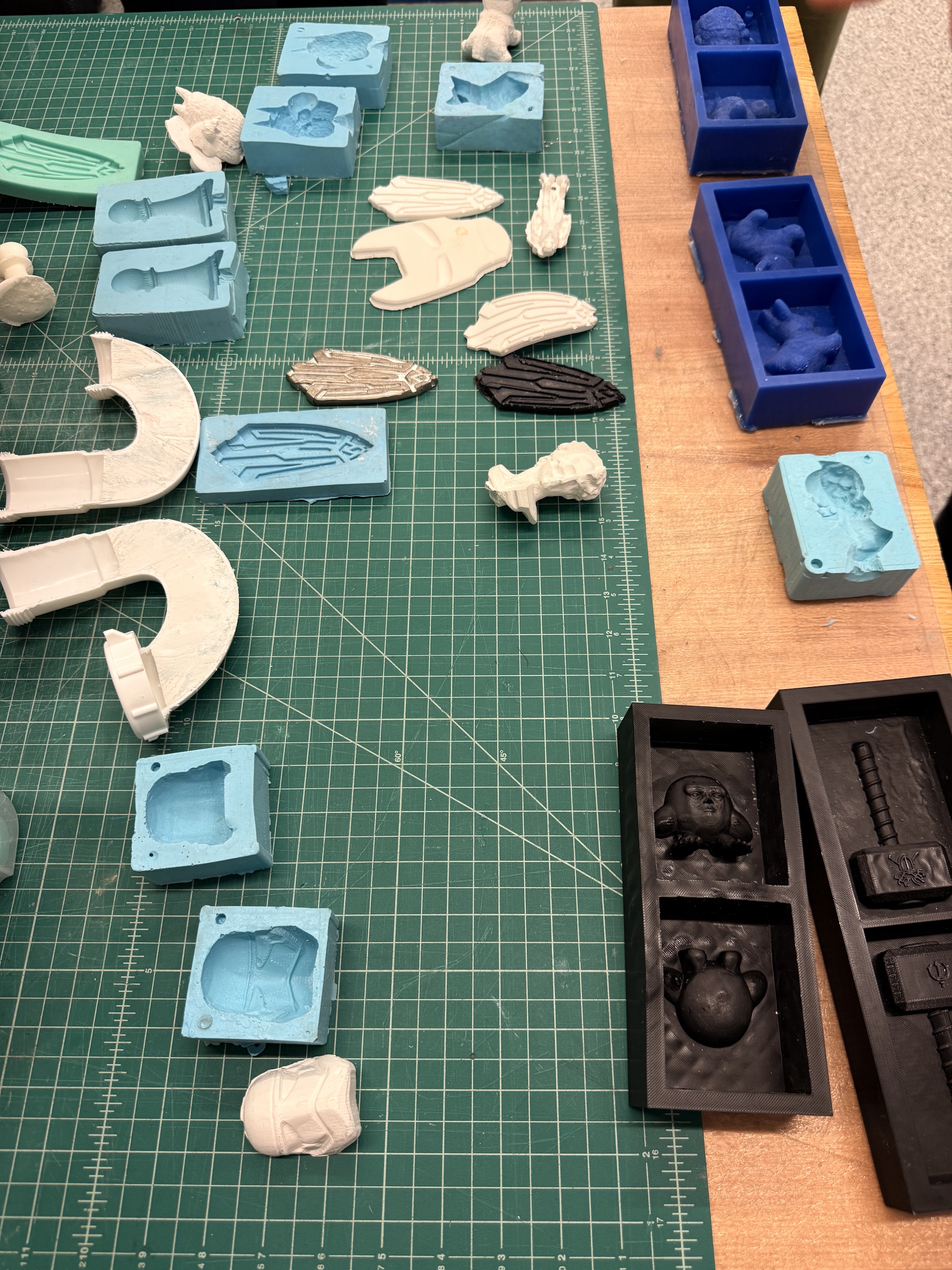
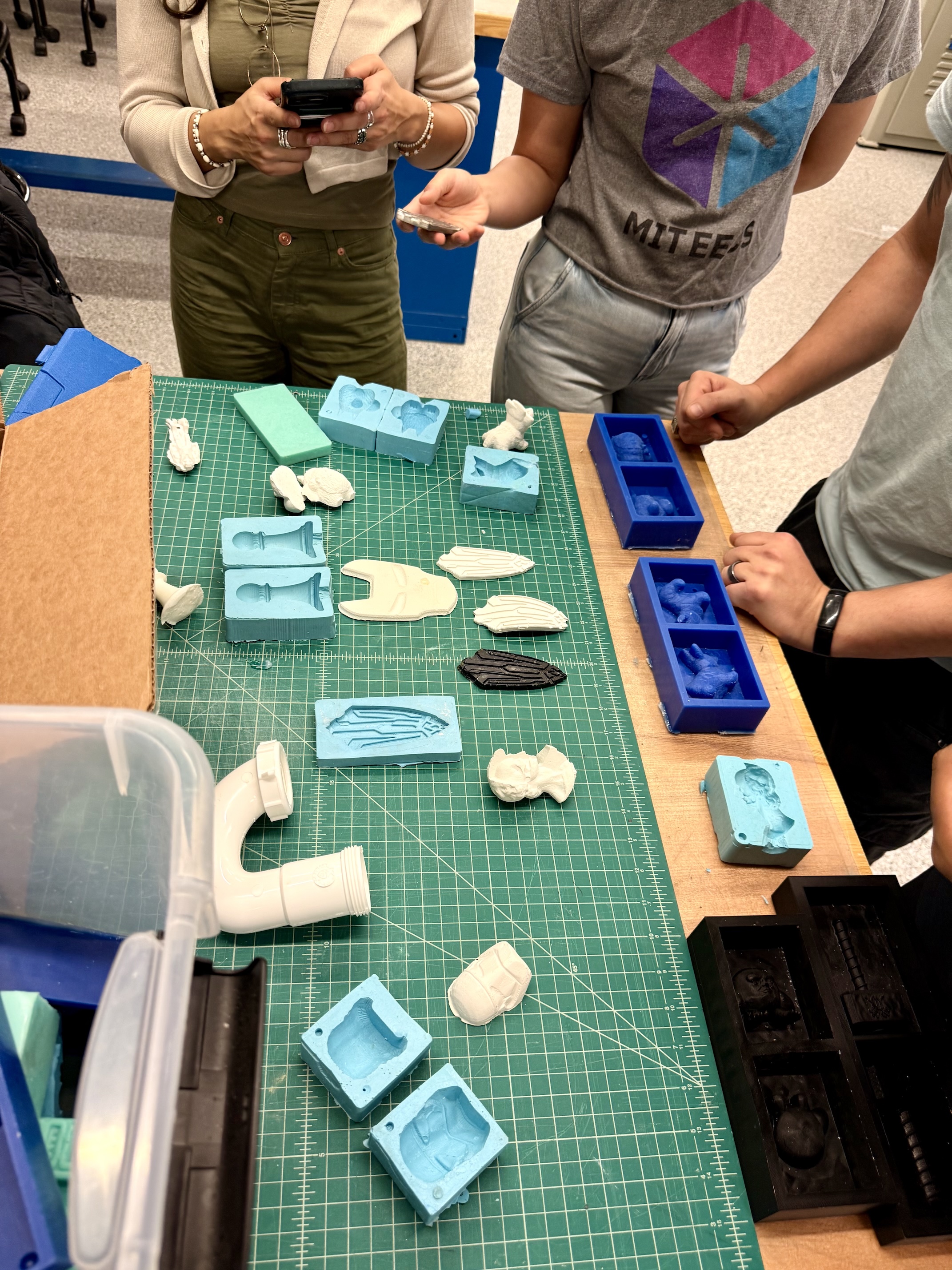
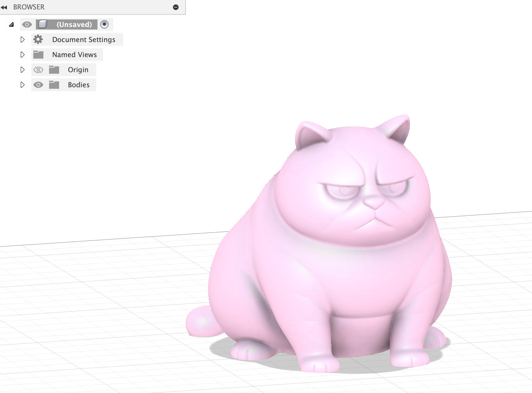
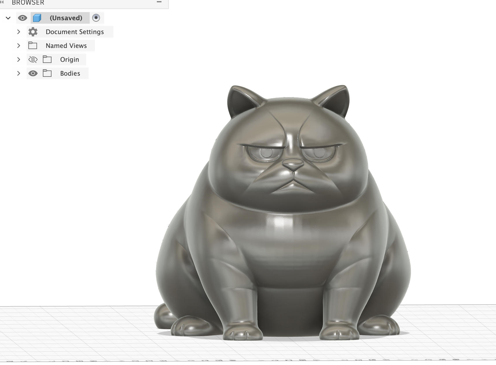
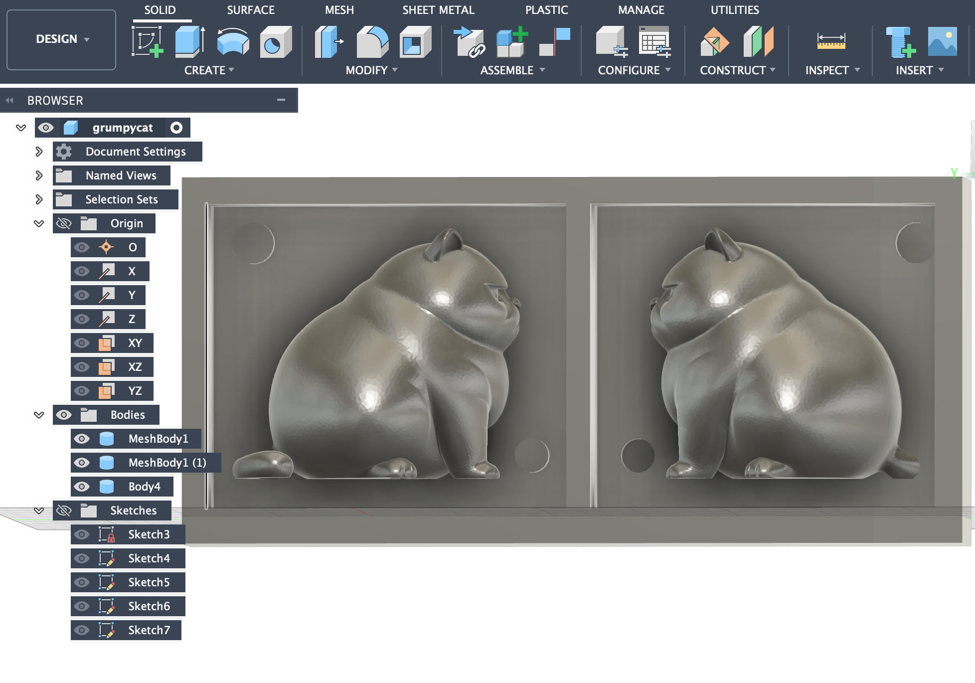
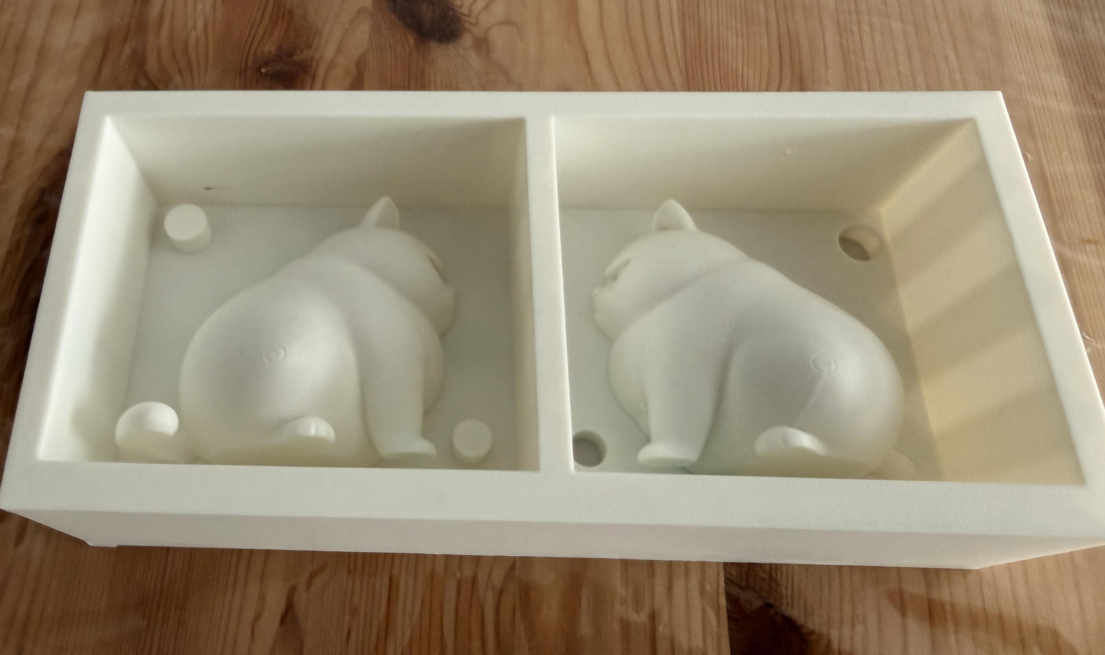
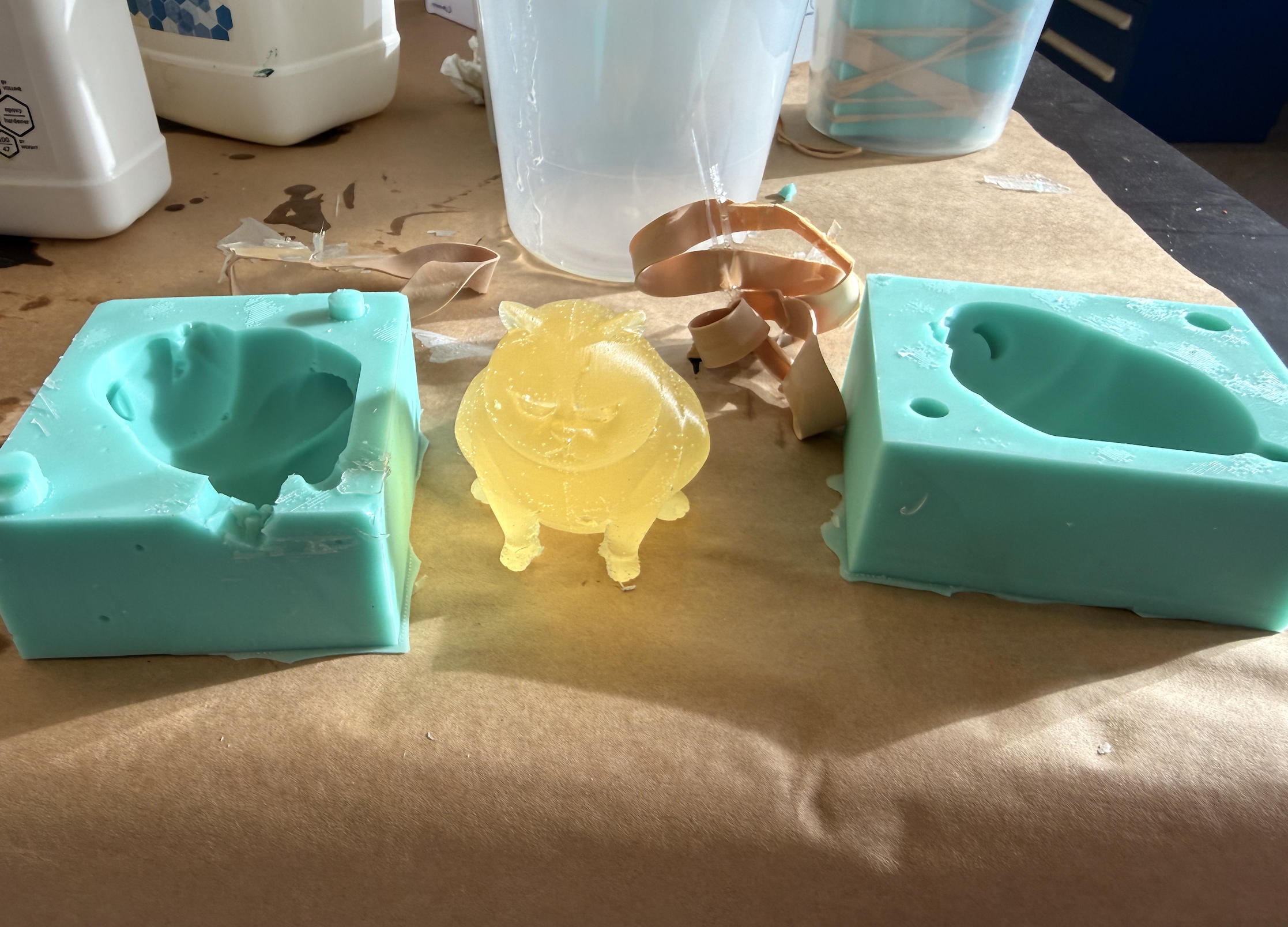
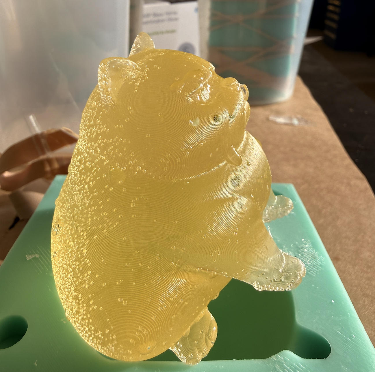
Project 2: Multi-part Mold - Grumpy Cat
Anthony made a video to show how multi-part mold can be constructed in Fusion 360:
My grumpy cat project is essentially the same as what Anthony showed in the video.

Files Download
Grumpy Cat 3mf file: download
Grumpy Cat stl file: download
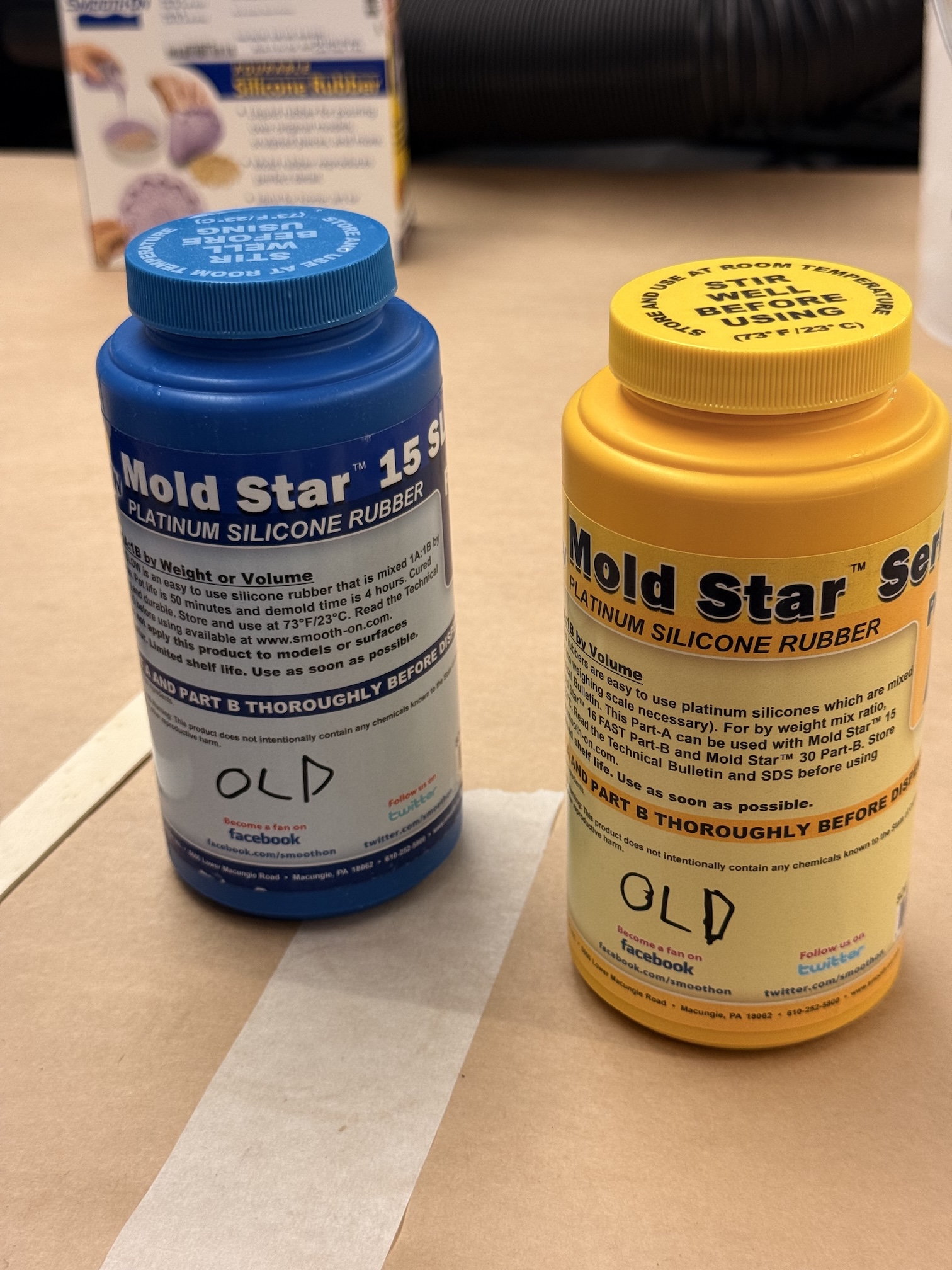
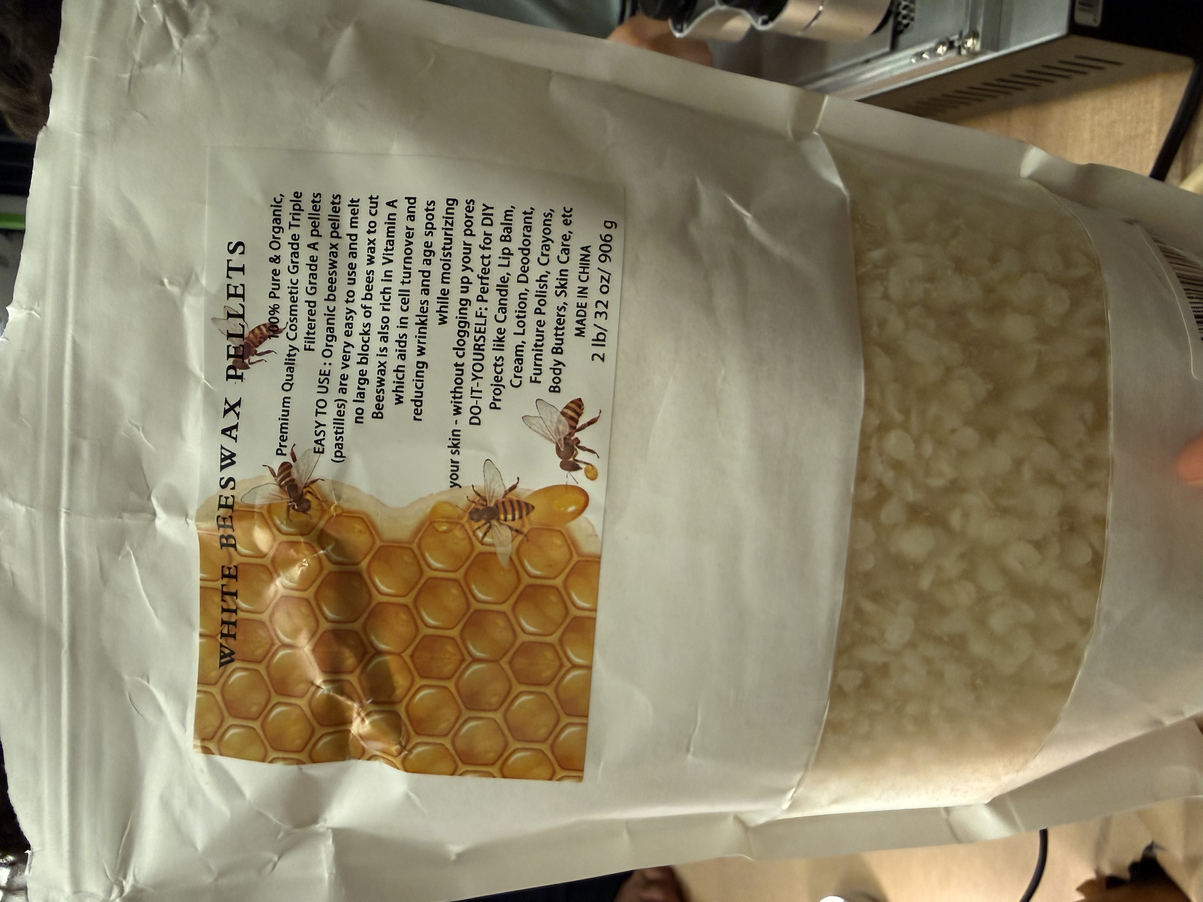
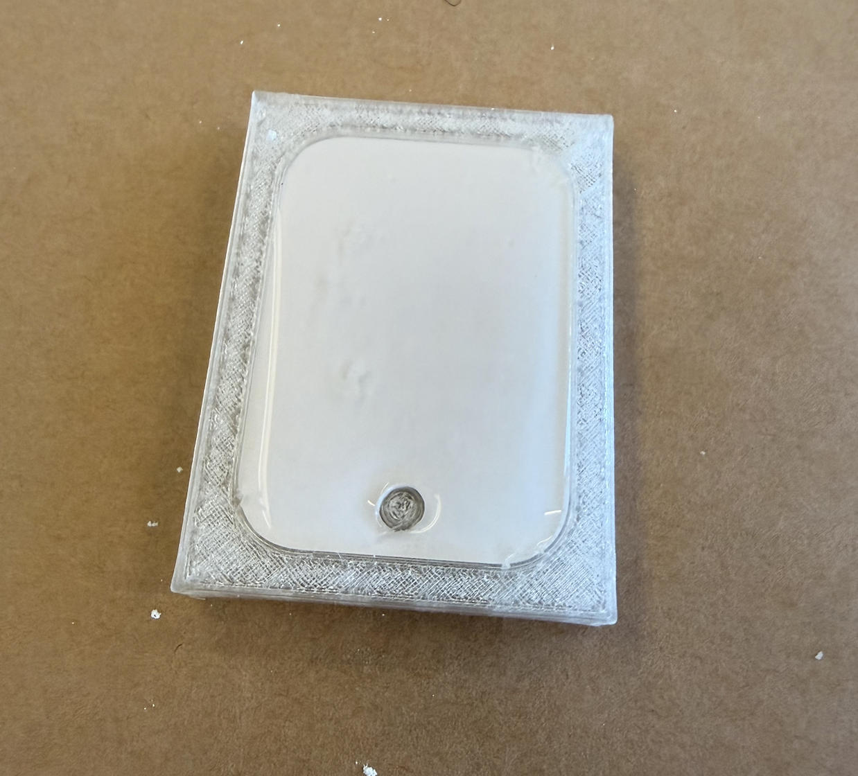
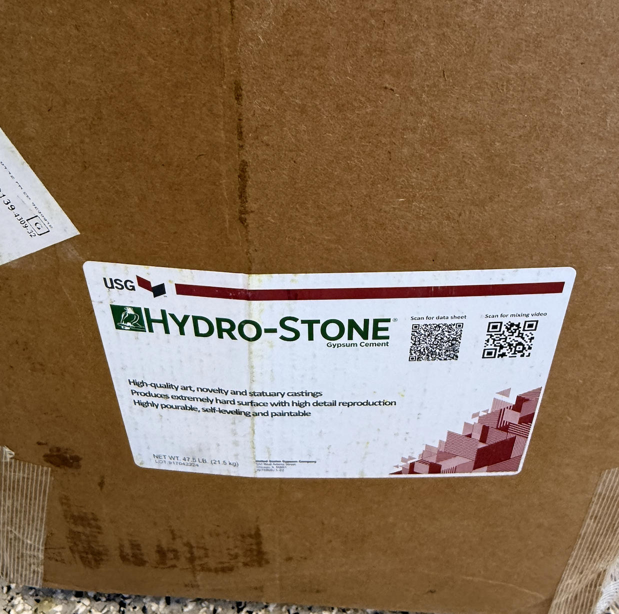
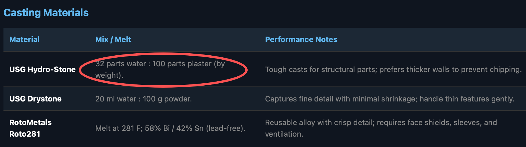
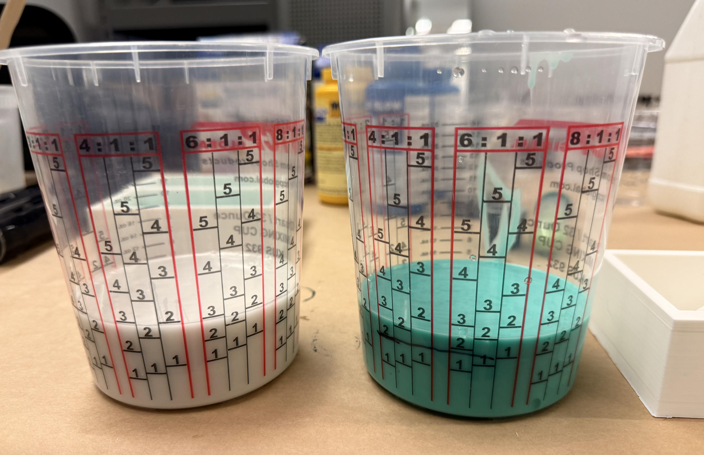
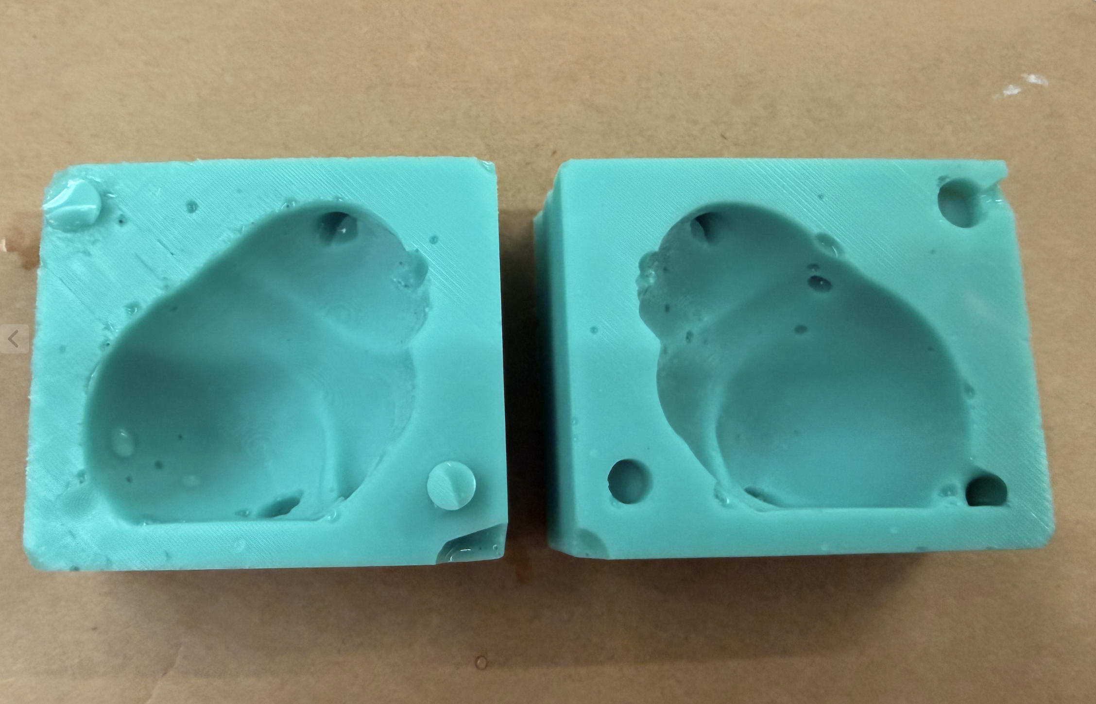
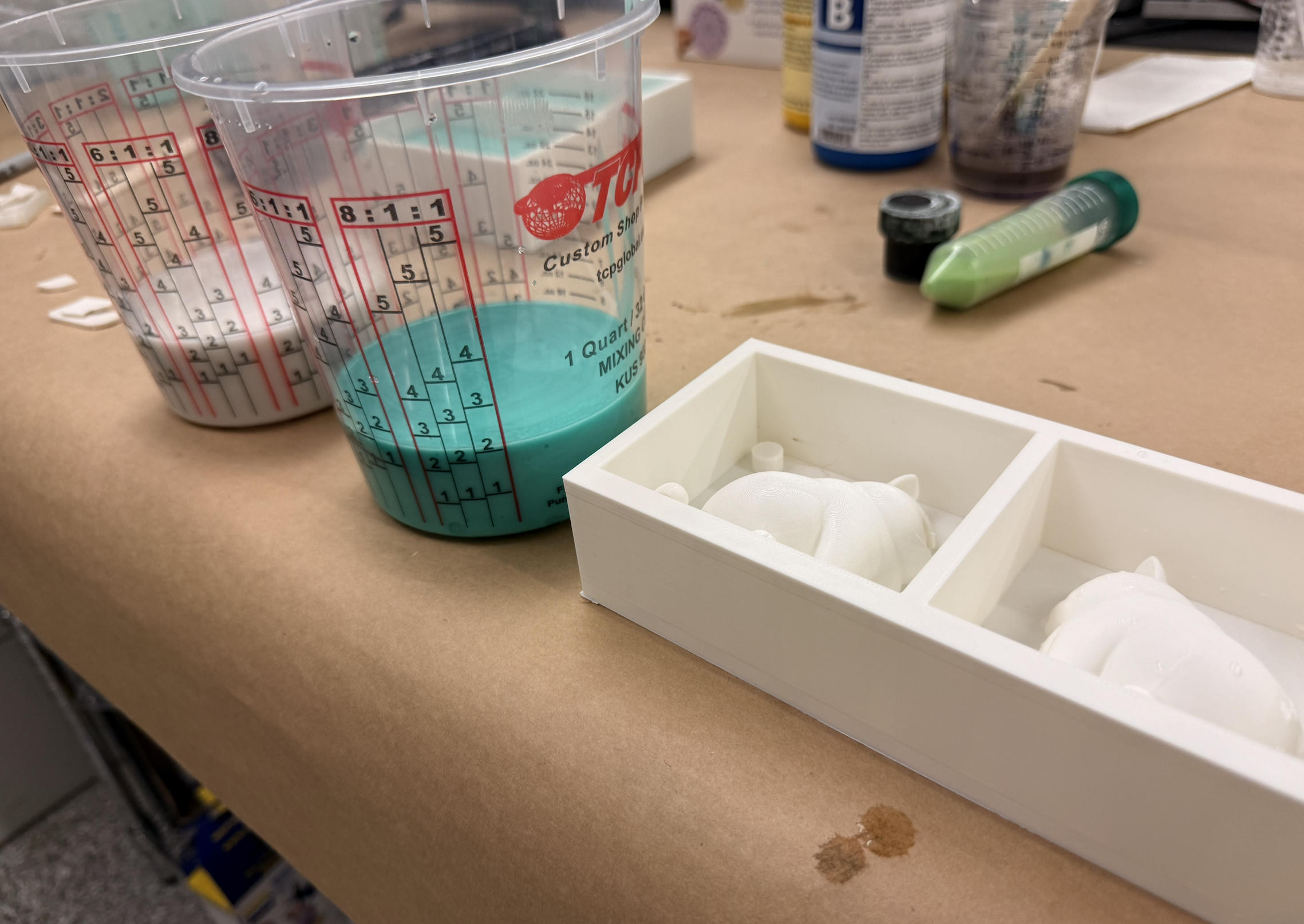
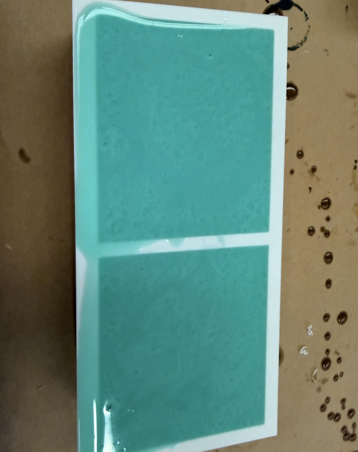
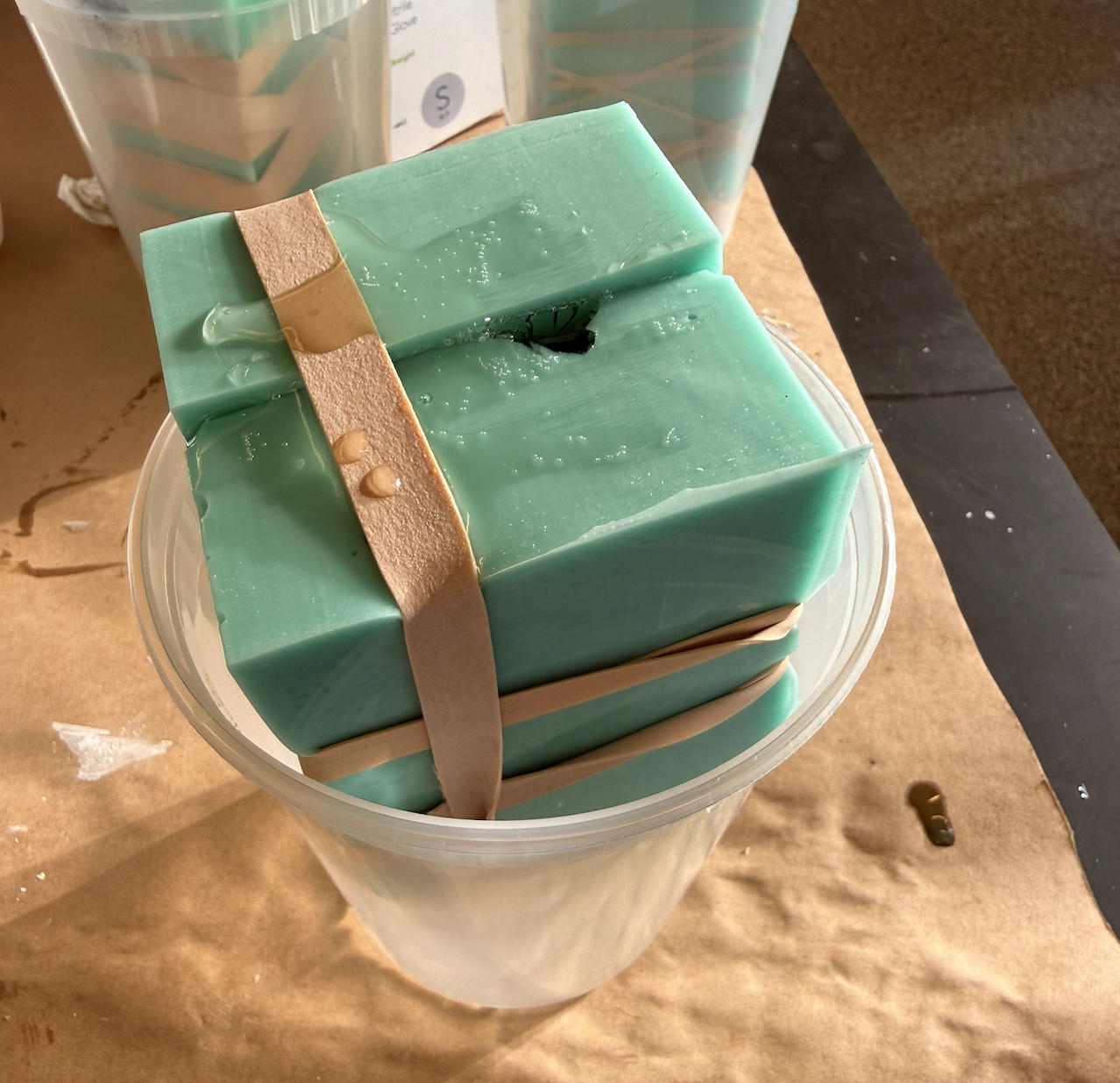
Casting
